📦 FactoryBox – Quickstart Guide for Beginners
Welcome! This guide helps you quickly start programming an ESP32 microcontroller using a pre-wired “FactoryBox” – a beginner-friendly setup with LEDs, buttons, sensors, and displays connected to fixed GPIO pins.
❇️ No wiring required! Just focus on coding.
We’ll use the Arduino framework together with PlatformIO (PIO) – a powerful yet easy-to-use coding environment that’s especially popular among beginners and hobbyists.
The FactoryBox includes not only the ESP32 itself, but also an I2C GPIO expander (MCP23018) that gives you extra input/output pins – perfect for adding more LEDs or buttons when the ESP32’s GPIOs run out.
While this guide was created specifically for the FactoryBox, most of the examples and explanations apply just as well to any ESP32-based project.
If you’re using a different setup – or just learning how to program an ESP32 – you’ll still find this guide helpful.
If you’re completely new to ESP32, Arduino, and PlatformIO, we recommend reading through this guide first to get comfortable with the basics.
But feel free to dive right in and experiment – if you ever get stuck, you can always come back here to find help.
You will learn how to:
- Control LEDs and motors
- Read sensors
- Display information on screens
- Write your own creative programs to bring the box to life
This guide is a practical starting point designed for experimentation. As you grow more confident, explore links to advanced topics or search online to expand your ideas.
🔗 Jump to: 📑 Table of Contents
🚀 Examples – Your Starting Point
Not sure where to start? Explore the examples folder in this repository. Each example demonstrates how to use a specific component of your FactoryBox – perfect starting points for your own projects.
Try uploading one of these ready-made examples directly to your board and see immediate results!
If the example requires you to install additional libraries, these will be clearly mentioned in comments within the code.
Blink an LED – Your First Example
Let’s start by blinking an LED – the “Hello World” of hardware programming:
#include <Arduino.h>                // include Arduino library
const int LED_PIN = 23;             // the number of the LED GPIO pin

void setup() {
  pinMode(LED_PIN, OUTPUT);         // initialize the LED pin as an output
}

void loop() {
  digitalWrite(LED_PIN, HIGH);      // turn the LED on
  delay(1000);                       // wait for 500 milliseconds
  digitalWrite(LED_PIN, LOW);       // turn the LED off
  delay(1000);                       // wait for 500 milliseconds
}
- Create a new PlatformIO project (as explained below)
- Copy and paste this code into your main.cpp
- Upload it
- Watch the LED blink every second!
Need to find the right GPIO pin for your component?
The GPIO Pinout shows all pins for the ESP32 and MCP23018 in the FactoryBox.
📑 Table of Contents
Getting Started
Background & Hardware
IDE & Programming
🧠 ESP32 – Microcontroller
Meet the brain of your FactoryBox:

This chapter introduces the ESP32 microcontroller, highlights its key features, and gives an overview of its GPIO pins and the functions they can perform.
🔎 Hardware Overview
The ESP32 is a low-cost, ultra-low power microcontroller with integrated Wi-Fi and dual-mode Bluetooth. It is suitable for a wide variety of applications–from low-power sensor networks to voice encoding, music streaming, and MP3 decoding. The ESP32 is a successor to the ESP8266 and is produced by Espressif Systems.
Key Features:
- Dual-core 32-bit processor (up to 240 MHz)
- 520 KB SRAM (Static RAM, for variables and data)
- Built-in Wi-Fi and Bluetooth (Classic + BLE)
- Many GPIOs with support for PWM, ADC, DAC, SPI, I2C, UART, and more
- Deep sleep mode for energy saving
Generally, you will use a development board with an ESP32 chip that includes a USB-to-serial converter, a voltage regulator, and pin headers. The development board for this project is equipped with the ESP-WROOM-32 module.
To expand the number of available GPIOs, the FactoryBox also includes an MCP23018 I2C GPIO expander. This chip connects to the ESP32 over the I2C bus and adds 16 additional digital input/output pins. It’s ideal for components that don’t need to be connected directly to the ESP32, helping you save valuable GPIO pins for more critical or timing-sensitive tasks.
Last Minute Engineers’ Getting Started with ESP32 guide provides a well-structured and detailed introduction to the ESP32, complete with practical examples and various use cases that will appeal to both beginners and experienced users.
🔗 Jump to: 🧠 ESP32 · 📑 Table of Contents
🧭 General Pin Layout
The ESP32 features a versatile set of GPIO pins, each with specific functions and limitations.
You can configure these pins as inputs or outputs using the pinMode() function. Once configured, you can read their state with digitalRead() or set their state with digitalWrite().
For more details on these functions, please see the dedicated section: 💡 Common Functions You’ll Use.
The internal registers also allow you to enable built-in pull-up or pull-down resistors, offering a flexible platform for interfacing with various sensors and actuators.
The diagrams and tables below help you identify which pins are available for your projects:
")
While the internal GPIO numbers (like GPIO23) are consistent across all ESP32 development boards, the physical layout (pin position and labeling) may vary depending on your specific board. The pinout images below show a common layout, but they may not be a 1:1 match with your board’s exact design.
🔗 Jump to: 🧠 ESP32 · 📑 Table of Contents
✅ Pins safe to use
Some ESP32 pins are reserved for specific purposes (e.g., internal flash memory, boot mode selection, input-only) and should not be used for general-purpose I/O. Check the pin reference carefully before using a pin in your project.
")
")
For detailed information about the pins, please refer to the ESP32 Pinout Reference by Last Minute Engineers, which gives a great overview of the ESP32 pin layout and the different functions of the pins. You can also consult the datasheet of the ESP32 Dev Board you are using.
🔗 Jump to: 🧠 ESP32 · 📑 Table of Contents
🔌 MCP23018 – GPIO Expander
The MCP23018 is an I2C-based GPIO expander used in the FactoryBox to provide 16 additional digital input/output pins – ideal for connecting more buttons, LEDs, and basic output components when your ESP32 runs out of GPIOs.

Key Features:
- Wide Voltage Compatibility: Operates over a broad range (typically 2.5V to 5.5V), ensuring seamless integration with both 3.3V and 5V systems.
- Built-In Pull-Up Resistors: Helps stabilize input signals without requiring extra external components.
- Open-Drain Outputs: Designed to pull lines low, perfect for many basic applications but requiring external circuitry if a push-pull high is needed.
The chip communicates with the ESP32 over the I2C bus using only two dedicated pins (SDA and SCL), helping conserve precious microcontroller resources.
New to I2C? Check out the official Arduino I2C (Wire) Documentation to understand how I2C communication works and how to use it in your own projects.
By integrating the MCP23018, you can significantly expand your system’s I/O capabilities without using up additional ESP32 pins – leaving more room for time-sensitive tasks or other peripherals.
Datasheet:MCP23018 – I2C GPIO Expander (Microchip)
📌 GPIO Structure and Configuration
The 16 GPIOs are split into two 8-bit ports (see image above):
- Port A: GPA0 to GPA7
- Port B: GPB0 to GPB7
Each pin can be individually configured as an input or output, and the expander’s registers allow you to set the direction, enable built-in pull-ups, and read or write the pin states.
Although you can manipulate these registers directly, it’s common to use a library (e.g. MCP23017_WE by Wolfgang Ewald) which abstracts away the low-level details. This way, after setup you can control the pins just like you would the ESP32’s native GPIOs.
Check out this example to see how a simple button can control a buzzer using the MCP23018.
I2C Address:
0x20The MCP23018 features a multi-bit analog address decoder, allowing up to eight unique I2C addresses using just a single address pin (ADDR).
It selects the address based on the voltage level present on ADDR, using an internal voltage comparator.
In the FactoryBox, this pin is connected to GND, so the MCP23018 uses the address
0x20.
Not all components are suitable for the MCP23018!
Its outputs are open-drain, which means it can pull a line low but not drive it high.
This is fine for LEDs, buttons and buzzers (or similar), but won’t work with components like servos, NeoPixels, or other devices that require push-pull or precisely timed signals.
For more flexible output capabilities, consider using the MCP23017 instead.
It features push-pull outputs (making it suitable for a wider range of components) and is even more popular in the maker community.
It also supports up to eight devices on the I2C bus using simple address pins (A0–A2), making configuration easier than with the MCP23018.
🔗 Jump to: 🔌 MCP23018 – GPIO Expander · 📑 Table of Contents
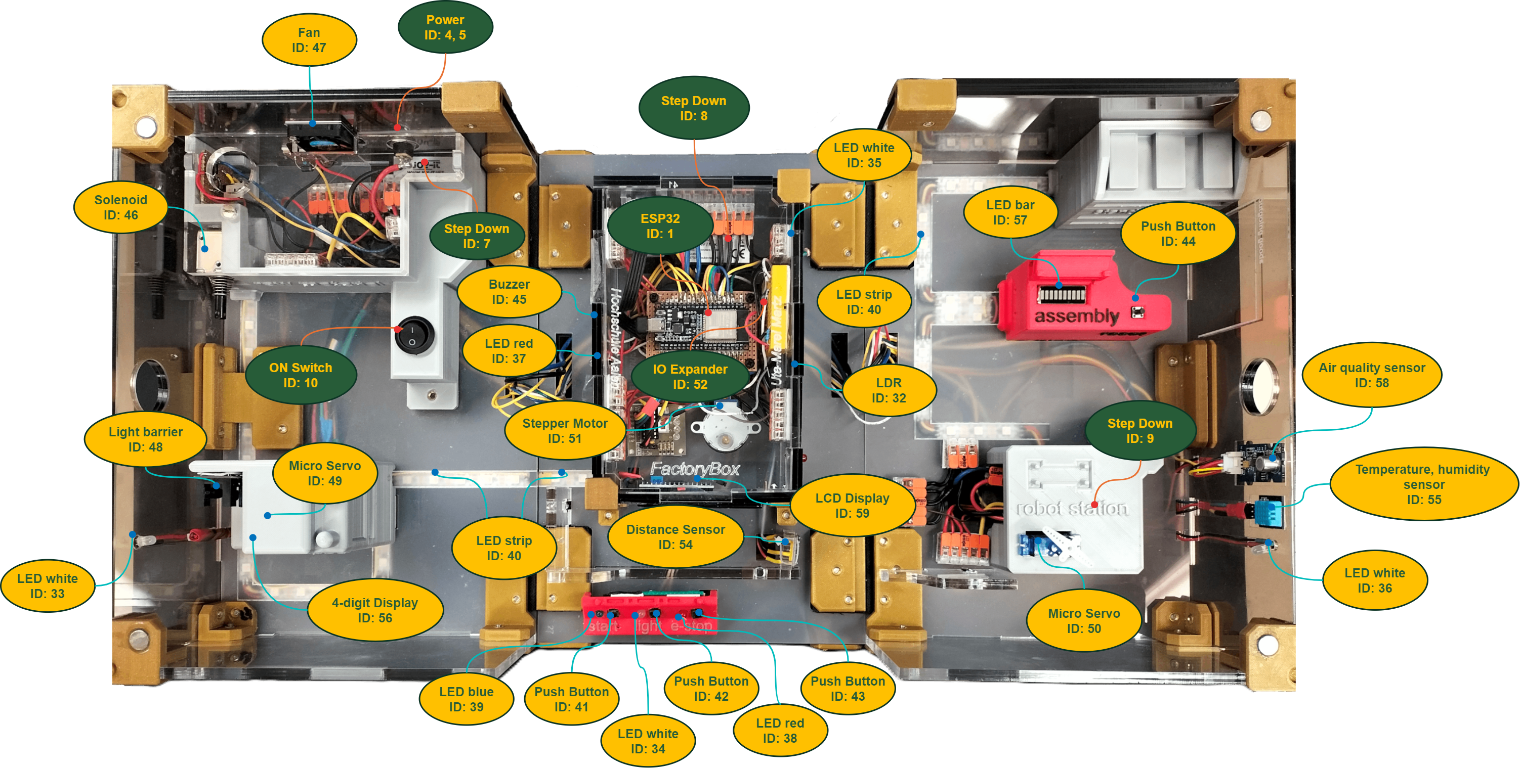
🧰 FactoryBox
The FactoryBox is a pre-wired learning environment built around the ESP32.
It includes LEDs, buttons, sensors, displays, and other components connected to specific GPIO pins.
All hardware is fixed – you don’t need to wire anything yourself.
This guide uses those predefined pin numbers in all examples.
📌 GPIO Pinout
Each component in the FactoryBox is wired to a specific GPIO pin on the ESP32 and MCP23018.
The table below shows which pin is used for what – so you don’t need to guess or trace any wiring.
The Part-ID relates to the Table electronic_parts_list.xlsx of the building-files repository and shows you the exact part we used.
You’ll use these GPIO numbers directly in your code when controlling LEDs, reading sensors, or displaying data.
The Part-ID refers to the table
electronic_parts_list.xlsx in the building-files repository.It identifies the exact components used in this FactoryBox – useful if you want to look up more information about a part online, or if you’re trying to source the correct parts to rebuild the system exactly.
🧠 ESP32 GPIO Pinout
| GPIO | Part | Part-ID | Area | Input/Output |
|---|---|---|---|---|
| 36 | LDR | 32 | 2 | Input, Analog |
| 39 | Photoelectric Counter | 48 | 1 | Input, Digital |
| 34 | Grove Air Quality Sensor | 58 | 3 | Input, Analog |
| 35 | Push Button #4 (Reset) | 44 | 3 | Input, Digital |
| 32 | Stepper Motor with Driver – IN4 | 51 | 2 | Output, Digital |
| 33 | Stepper Motor with Driver – IN3 | 51 | 2 | Output, Digital |
| 25 | Stepper Motor with Driver – IN2 | 51 | 2 | Output, Digital |
| 26 | Stepper Motor with Driver – IN1 | 51 | 2 | Output, Digital |
| 27 | Solenoid | 46 | 1 | Output, Digital |
| 14 | Fan | 47 | 1 | Output, analog (PWM) |
| 12 | NC | NC | NC | NC |
| 13 | RGBW LED Strip (SK6812) | 40 | 1 | Output, Digital |
| 15 | NC | NC | NC | NC |
| 2 | Servo #1 | 49 | 1 | Output, analog (PWM) |
| 0 | NC | NC | NC | NC |
| 4 | Servo #2 | 50 | 3 | Output, analog (PWM) |
| 16 | Grove 4-Digit Display – DCLK | 56 | 1 | Output, Digital |
| 17 | DHT11 | 55 | 3 | Bidirectional, Digital |
| 5 | Grove 4-Digit Display – DIO | 56 | 1 | Output, Digital |
| 18 | Grove LED-Bar – DI | 57 | 3 | Output, Digital |
| 19 | Grove LED-Bar – DCKI | 57 | 3 | Output, Digital |
| 21 | MCP23018 (I2C GPIO Expander) – SDA | 52 | 2 | I2C (Digital) |
| 21 | I2C LCD Display – SDA | 53 | 2 | I2C (Digital) |
| 21 | I2C TOF Sensor – SDA | 54 | 2 | I2C (Digital) |
| 3 | NC | NC | NC | NC |
| 1 | NC | NC | NC | NC |
| 22 | MCP23018 (I2C GPIO Expander) – SCL | 52 | 2 | I2C (Digital) |
| 22 | I2C LCD Display – SCL | 53 | 2 | I2C (Digital) |
| 22 | I2C TOF Sensor – SCL | 54 | 2 | I2C (Digital) |
| 23 | LED White #3 (Lighting) | 36 | 3 | Output, Digital |
NC = Not Connected
Area: 1 = Incoming Goods, 2 = Manufacturing, 3 = Outgoing Goods
🔗 Jump to: 🧰 FactoryBox · 📑 Table of Contents
🔌 MCP23018 GPIO Pinout
| GPIO | Part | Part-ID | Area | Notes |
|---|---|---|---|---|
| B0 | Push Button #1 (Start/Stop) | 41 | 2 | Input, Digital |
| B1 | LED Blue (Start/Stop) | 39 | 2 | Output, Digital |
| B2 | Push Button #2 (Light Switch) | 42 | 2 | Input, Digital |
| B3 | LED White #4 (Light Switch) | 34 | 2 | Output, Digital |
| B4 | Push Button #3 (Emergency Stop) | 43 | 2 | Input, Digital |
| B5 | LED Red #2 (Emergency Stop) | 38 | 2 | Output, Digital |
| B6 | LED White #1 (Lighting) | 33 | 1 | Output, Digital |
| B7 | NC | NC | NC | NC |
| A0 | NC | NC | NC | NC |
| A1 | NC | NC | NC | NC |
| A2 | NC | NC | NC | NC |
| A3 | NC | NC | NC | NC |
| A4 | NC | NC | NC | NC |
| A5 | LED Red #1 (Alert TOF Sensor) | 37 | 2 | Output, Digital |
| A6 | Buzzer (Alert TOF Sensor) | 45 | 2 | Output, Digital |
| A7 | LED White #2 (Lighting) | 35 | 2 | Output, Digital |
NC = Not Connected
Area: 1 = Incoming Goods, 2 = Manufacturing, 3 = Outgoing Goods
I2C Address:
0x20The MCP23018 uses the I2C address
0x20 in the FactoryBox. For more details, see
🔌 MCP23018 – GPIO Expander.
🔗 Jump to: 🧰 FactoryBox · 📑 Table of Contents
🧑💻 PlatformIO IDE
This chapter walks you through using PlatformIO with Visual Studio Code to create, open, and manage projects for your ESP32.
- ➕ Create a New Project
- 🟰 Open an Existing PlatformIO Project
- 📁 Project Folder Structure
- 📚 Libraries
- 🏃➡️ Run Your Code
🔎 Overview
PlatformIO is an open-source, cross-platform IDE specifically designed for embedded software development. It features built-in library management, extensive ESP32 support, and compatibility with the Arduino framework.
This guide uses PlatformIO with Visual Studio Code. While the provided code is generally compatible with the Arduino IDE, note there may be minor differences in project structure and library handling.
Need more details on setting up or troubleshooting PlatformIO in VS Code? Check the official documentation: PlatformIO IDE for VS Code.

➕ Create a New Project
To get started, let’s create a new PlatformIO project for your ESP32 board:
- Open PlatformIO Home
- Click on “New Project”
- Choose a board: Type “esp32 dev” in the search bar and select “Espressif ESP32 Dev Module”
- Choose the Arduino framework (default)
- Choose a project location by unchecking “Use default location” and selecting a folder
- Click “Finish”

Once your project is created and opened, you’ll see its name appear in the bottom bar of VS Code (e.g., Default (demo_project)), confirming that your new project is active:

🔗 Jump to: 🧑💻 PlatformIO IDE · 📑 Table of Contents
🟰 Open an Existing PlatformIO Project
Want to continue working on an existing project? Here’s how to open it in PlatformIO.
- Open PlatformIO Home
- Click on “Open Project”
- Select the project folder that contains the platformio.ini file
- Click “Open”

When the project is loaded, its name will also appear in the bottom bar, just like with a newly created project:

🔗 Jump to: 🧑💻 PlatformIO IDE · 📑 Table of Contents
📁 Project Folder Structure
When you create or open a PlatformIO project (e.g., 01_led_blink), you’ll see a folder structure like this:

Here’s what each folder is for:
src/– This is where your main code goes. Your entry point ismain.cpplib/– Custom libraries you create for your project, or manually add (e.g. downloaded from GitHub)include/– Header files (.h) for declaring functions, constants, etc.pio/– PlatformIO uses this folder internally to store build output (build/) and libraries installed via the library manager (libdeps/)platformio.ini– Your project’s configuration file (defines board type, libraries, build settings)
For your programs, focus on writing your code in src/main.cpp.
PlatformIO automatically compiles and uploads the contents of that file to your ESP32.
🔗 Jump to: 🧑💻 PlatformIO IDE · 📑 Table of Contents
📚 Libraries
PlatformIO uses a library manager to browse and install libraries. Libraries are installed per project, so you can have different libraries in different projects. They are listed in the platformio.ini file under the lib_deps line and are stored in the .pio folder within your project directory. If you no longer need a library, you can uninstall it through the library manager.
Install a Library:
- Go to PlatformIO
- Click on “Libraries”
- Open the “Registry” tab
- Search for the library you want to install
- Click on the library
- Click “Add to Project”
- Choose your project
- Click “Add”
Uninstall a Library:
- Go to PlatformIO
- Click on “Libraries”
- Open the “Installed” tab
- Locate the library you want to uninstall (make sure you select the correct project)
- Click “Uninstall” and confirm with “Yes”

In some cases, the version of a library in the PlatformIO Library Manager may be outdated, while a newer version is available on GitHub. If you want to use the GitHub version instead, you can add it manually to your project:
Manually Install a Library from GitHub:
- Copy the GitHub repository URL of the library you want to use
- Open the
platformio.inifile of your project - Add the URL to the
lib_depsline, for example:lib_deps = https://github.com/Seeed-Studio/Grove_LED_Bar.git - Save the file
- The library will be automatically downloaded and installed when you build or upload your code
- You can find the installed library inside the
libfolder of your project

🔗 Jump to: 🧑💻 PlatformIO IDE · 📑 Table of Contents
🏃➡️ Run Your Code
Once your code is ready, you can upload it to your ESP32 board:
- Make sure the correct project is selected in the bottom bar (e.g.,
Default (01_led_blink)). - Click the ➡️ Upload button (right arrow icon) in the bottom bar to build and flash your code to the ESP32.
- Optionally, you can click the ✅ Build button first (checkmark icon) to compile the code without uploading – useful if you just want to check for errors.
- Open the Serial Monitor (plug icon) to view messages from
Serial.print()and other serial output.

Make sure your board is connected via USB and the correct COM port is selected (PlatformIO usually detects this automatically).
If your ESP32 doesn’t respond during upload, press and hold the BOOT button on your board when you see “Connecting…” in the terminal.
If you don’t see any messages in the Serial Monitor, double-check that you’ve included
Serial.begin(9600); in your setup() function, and ensure the baud rate (e.g., 9600) matches the one selected in your Serial Monitor settings.
🔗 Jump to: 🧑💻 PlatformIO IDE · 📑 Table of Contents
🧩 Arduino Code Structure
A typical Arduino sketch consists of three main parts:
/*
     1. Include libraries, define constants, declare global variables, etc.
*/

void setup() {
  // 2. This function runs once when the device starts or resets.
}

void loop() {
  // 3. This function runs repeatedly after setup() and contains your main code.
}
When using PlatformIO, you must include the
Arduino.h library to access standard Arduino functions (this is not required in the Arduino IDE).
1. Libraries and Definitions
Start by including all necessary libraries and defining global constants, variables, and objects. This section is where you set up anything that will be used throughout your program.
Example:
#include <Arduino.h>  // Essential for PlatformIO projects (Arduino IDE automatically includes this).
#include <ExampleLibrary.h>  // Replace with the libraries you need

// Define constants for hardware connections. These values should not change.
const int LED_PIN = 23;  // Example: assign the LED to GPIO pin 23

// Declare global variables that can change during program execution.
int exampleVariable = -1;  // Example variable initialized to -1
🔗 Jump to: 🧩 Arduino Code Structure · 📑 Table of Contents
2. The Setup Code
The setup() function is executed once when the ESP32 (or any Arduino board) starts or resets. Use this function to initialize serial communication, configure pin modes, and set initial states for variables.
Example:
void setup() {
  Serial.begin(9600);          // Initialize serial communication at 9600 baud for debugging.
  Serial.println("LED Blink"); // Output an initial message to the Serial Monitor.

  pinMode(LED_PIN, OUTPUT);    // Configure the LED pin as an output.

  // Additional setup code (e.g., sensor initialization) can be added here.
}
🔗 Jump to: 🧩 Arduino Code Structure · 📑 Table of Contents
3. The Loop Code
The loop() function runs continuously after setup() finishes. It contains the main logic of your program and will repeat until the board is powered off or reset.
Example:
void loop() {
  // Turn the LED on, print a message, and wait.
  digitalWrite(LED_PIN, HIGH);   // Activate the LED.
  Serial.println("LED ON");      // Output current status to the Serial Monitor.
  delay(1000);                   // Wait for 1 second (1000 milliseconds).

  // Turn the LED off, print a message, and wait.
  digitalWrite(LED_PIN, LOW);    // Deactivate the LED.
  Serial.println("LED OFF");     // Output current status to the Serial Monitor.
  delay(1000);                   // Wait for 1 second.
}
This structure helps keep your code organized, making it easier to manage and expand your projects.
🔗 Jump to: 🧩 Arduino Code Structure · 📑 Table of Contents
💡 Common Functions You’ll Use
This section covers the most common functions you’ll use regularly in your ESP32 projects:
- 📌 Pin Configuration
- 💬 Serial Communication
- 📝 Read/Write Data
- ⏱️ Timing and Logic
- 🧮 Utility Functions
- 📖 Further Learning
📌 Pin Configuration
Learn how to define pins and configure them correctly for input and output:
- Define a Pin
- Create a named constant for a pin to make your code more readable and easier to maintain.
- Example:
const int LED_PIN = 2; // Replace 2 with the actual GPIO pin number you want to use
- pinMode(pin, mode)🔗
- Configures a specified pin to behave as either an input or an output.
- Example:
pinMode(LED_PIN, OUTPUT);
pinMode(BUTTON_PIN, INPUT_PULLDOWN);
Not sure which GPIO pin number to use?
See GPIO Pinout to find all pin assignments for the ESP32 and MCP23018 in your FactoryBox.
🔗 Jump to: 💡 Common Functions You’ll Use · 📑 Table of Contents
💬 Serial Communication
Easily debug your code by printing messages to the Serial Monitor:
Serial communication allows you to send data to the Serial Monitor for debugging or logging purposes. Below are the most commonly used functions and when to use them:
- Serial.begin(baudRate)🔗
- Required! This function must be called once in the
setup()function to initialize serial communication. - If you don’t call
Serial.begin(), none of the other serial functions (print,println,printf) will work – you won’t see any output in the Serial Monitor. - Example:
- Required! This function must be called once in the
Serial.begin(9600); // Initialize serial communication at 9600 baud
- Serial.print(data)🔗
- Sends data as human-readable ASCII text without a newline at the end.
- Memory Note: Literal strings not wrapped in the
F()macro are stored in RAM. UseF("string")to store strings in Flash memory and save RAM. - Example:
float temperature = 23.456;
int humidity = 45;

Serial.print("Hello, world!");    // Prints a string from SRAM
Serial.print(F("Hello, Flash!")); // Prints a string from Flash memory
Serial.print(temperature, 2);     // Prints a variable with 2 decimal places
Serial.print(humidity);           // Prints a variable
Output:
Hello, world!Hello, Flash!23.4645
- Serial.println(data)🔗
- Similar to
Serial.print(), but appends a carriage return and newline (\r\n) so that the next output begins on a new line. - Memory Note: As with
Serial.print(), useF()to move constant strings to Flash memory and save RAM. - Example:
- Similar to
float temperature = 23.456;
int humidity = 45;

Serial.println("Hello, world!");      // Prints the string and moves to a new line
Serial.println(F("Hello, Flash!"));   // Prints string stored in Flash and moves to a new line
Serial.println();                     // Prints a blank line and moves to a new line
Serial.println(temperature, 2);       // Prints a variable with 2 decimal places and moves to a new line
Serial.println(humidity);             // Prints a variable and moves to a new line
Output:
Hello, world!
Hello, Flash!

23.46
45
🔗 Jump to: 💡 Common Functions You’ll Use · 📑 Table of Contents
📝 Read/Write Data
Discover how to interact with sensors, buttons, LEDs, and more:
- digitalWrite(pin, value)🔗
- Writes a
HIGHorLOWvalue to a digital pin. - Example:
- Writes a
digitalWrite(LED_PIN, HIGH);  // Turn the LED on
digitalWrite(LED_PIN, LOW);   // Turn the LED off
- digitalRead(pin)🔗
- Reads the value (
HIGHorLOW) from a specified digital pin. - Example:
- Reads the value (
int buttonState = digitalRead(BUTTON_PIN);
int sensorReading = digitalRead(SENSOR_PIN);
- analogWrite(pin, value)🔗
- Writes an analog (PWM) value to a pin. On most boards, the default resolution is 8-bit (0 to 255).
- Example:
analogWrite(LED_PIN, 180); // Set LED brightness (0 = off, 255 = full brightness)
- analogRead(pin)🔗
- Reads the value from an analog pin. ESP32 analog inputs have a 12-bit resolution (0 to 4095).
- Example:
int sensorReading = analogRead(SENSOR_PIN);
🔗 Jump to: 💡 Common Functions You’ll Use · 📑 Table of Contents
⏱️ Timing and Logic
Essential tools to control the flow and timing of your program:
- delay(milliseconds)🔗
- Pauses the program for a set amount of time. Useful for blinking LEDs, debouncing buttons, and slowing down actions.
- Example:
digitalWrite(LED_PIN, HIGH);
delay(500);  // Wait 500 milliseconds (code execution is paused)
digitalWrite(LED_PIN, LOW);
delay(500);
While
delay() is simple and useful, it blocks your program – meaning no other code runs during the wait.If you need to do multiple things at once (like blinking an LED while checking a button), consider the non-blocking
millis() approach instead.
- if🔗 / else🔗 Statement (Conditional Statement)
- Control the flow of your program based on conditions. Perfect for checking sensor values, buttons, or states.
- Example:
if (buttonState == HIGH) {
  digitalWrite(LED_PIN, HIGH);  // LED on
} else {
  digitalWrite(LED_PIN, LOW);   // LED off
}
- for Loop🔗
- Use a
forloop when you want to repeat something a specific number of times or iterate over a range of values. - General Syntax:
- Use a
for (initialization; condition; increment) {
  // statement(s);
}

// A for-loop starts with an initialization, executed once.
// Then the condition is evaluated – if true, the loop body runs.
// After each run, the increment step is executed.
// This repeats until the condition becomes false, and the loop ends.
- Example:
// Blink an LED 5 times
for (int i = 0; i < 5; i++) {
  digitalWrite(LED_PIN, HIGH);
  delay(500);
  digitalWrite(LED_PIN, LOW);
  delay(500);
}

// Count from 0 to 4 and print the numbers
for (int i = 0; i < 5; i++) {
  Serial.println(i);
}

// Loop explanation:
// int i = 0: Initializes the loop counter i
// i < 5: The loop runs while this condition is true
// i++: Increments i by 1 after each loop cycle
🔗 Jump to: 💡 Common Functions You’ll Use · 📑 Table of Contents
🛠️ Utility Functions
Helpful built-in functions to simplify common tasks in your code:
- map(value, fromLow, fromHigh, toLow, toHigh)🔗
- Maps a number from one range to another.
- Example:
int ledValue = map(potiRead, 0, 4095, 0, 255);
// Maps the potentiometer value (0 to 4095, 12-bit) to the analogWrite range (0 to 255, 8-bit PWM)
- constrain(value, min, max)🔗
- Constrains a value to a specified range.
- Example:
int constrainedValue = constrain(sensorValue, 1000, 3000); // Limits the value between 1000 and 3000
🔗 Jump to: 💡 Common Functions You’ll Use · 📑 Table of Contents
📖 Further Learning
Want to go deeper?
Here are some official Arduino resources to help you learn more about programming, syntax, and best practices: Useful sections:
🔗 Jump to: 💡 Common Functions You’ll Use · 📑 Table of Contents
